01 — Embedded Hardware Architecture
Design the Platform Before Designing the Circuit
A high-quality embedded design begins with architecture.
Before detailed schematic capture, engineers need to determine:
What processing architecture is required?
What functions belong in hardware?
What functions belong in firmware?
How much memory is required?
What interfaces are required?
What performance margin is necessary?
What power architecture is appropriate?
What security architecture is required?
What thermal constraints exist?
What manufacturing and test strategy will be used?
The architecture may take many forms:
Single-MCU Architecture
For real-time control, sensing, low-power devices, industrial interfaces, and cost-sensitive products.
MCU + Wireless SoC
For connected embedded products.
MCU + FPGA
For deterministic control combined with high-speed or custom digital logic.
MPU + MCU
For Linux-class application processing combined with deterministic real-time control.
SoC + NPU
For Edge AI, computer vision, intelligent sensing, or local inference.
MPU + FPGA
For advanced data acquisition, communications, imaging, test equipment, and high-speed processing.
Heterogeneous Multi-Processor Architecture
For systems requiring multiple processing domains.
The Right Embedded Architecture Is the Foundation of the Entire Product.
02 — Processor Platform Selection
MCU, MPU, SoC, FPGA, DSP or NPU?
Processor selection should be driven by system requirements rather than brand familiarity.
Depending on the project, engineering may evaluate: MCU
ARM Cortex-M and other embedded platforms for:
Real-time control
Low power
Motor control
Industrial products
Sensor processing
Connectivity
Human-machine interfaces
MPU
For:
SoC
Where multiple processing, communications, graphics, multimedia, security, and acceleration functions are integrated.
FPGA
For:
For:
Digital filtering
Communications
Audio
Signal processing
Advanced control
NPU / AI Accelerator
For:
Edge AI
Computer vision
Local inference
Machine learning
Sensor intelligence
The objective is not: Which processor is the most powerful?
The better question is: Which Processing Architecture Best Matches Performance, Power, Cost, Thermal, Software, and Lifecycle Requirements?
03 — ARM / MCU Hardware Architecture
For MCU-based products, engineering can involve much more than placing a microcontroller onto a schematic.
The complete architecture may include:
CPU Core
Clock System
Reset
Power Domains
Flash
RAM
ADC / DAC
Timers
PWM
DMA
Communication Interfaces
Debug
Security
Boot Architecture
Key considerations may include:
Core performance
interrupt architecture
DMA capability
memory size
peripheral availability
low-power modes
analog peripherals
hardware crypto
package
temperature range
lifecycle
programming strategy
An MCU Is Not the Architecture.
It Is One Element Inside the Architecture.
04 — MPU & Application Processor Design
Higher-performance embedded products increasingly use application processors capable of running:
or other rich operating systems.
MPU hardware development can involve:
Compared with MCU systems, MPU platforms introduce substantially greater complexity in:
Power Sequencing
Memory Routing
Signal Integrity
Power Integrity
Thermal Design
Boot Architecture
and
PCB Stack-Up
A successful MPU product requires the processor, memory, PMIC, PCB, firmware and thermal architecture to be designed together.
05 — Heterogeneous Computing Architecture
Modern products increasingly use different processors for different workloads.
For example:
MPU
Runs Linux, networking and application software.
MCU
Handles real-time control and safety monitoring.
FPGA
Processes deterministic high-speed data.
NPU
Executes AI inference.
The challenge is not simply connecting them.
The system must define:
Arm's current AMBA architecture illustrates this broader industry direction, with AXI and CHI designed for high-bandwidth and coherent system interconnection, and CHI C2C extending coherent architecture toward chiplet-to-chiplet communication.
Heterogeneous Computing Requires System-Level Partitioning.
06 — Memory Architecture
Memory design can determine whether a processing platform actually achieves its expected performance.
Embedded memory systems may include:
Internal Memory
SRAM Embedded Flash Cache
External Volatile Memory
SDRAM, DDR3, DDR4, DDR5, LPDDR4 / LPDDR5
Non-Volatile Memory
NOR Flash, NAND Flash, EEPROM, eMMC, UFS
High-Capacity Storage
SD, SSD, NVMe
Engineering considerations may include:
capacity
bandwidth
latency
bus width
ECC
endurance
data retention
boot requirements
encryption
thermal behavior
PCB routing
signal integrity
A Powerful Processor Starved of Memory Bandwidth Is Not a Powerful System.
07 — DDR / LPDDR Hardware Design
High-speed memory design is one of the more demanding areas of embedded PCB engineering.
Important variables include:
The design must consider:
Controller Package
PCB
Memory Package
as one electrical channel.
For advanced DDR systems, pre-layout and post-layout SI analysis may be appropriate depending on performance and margin.
Memory Routing Is Timing Engineering.
08 — High-Speed Digital Interface Architecture
Modern embedded platforms may use:
These interfaces require more than logical connectivity.
They require engineering control of:
PCIe 7.0 now defines a 128 GT/s generation of PCI Express, illustrating how quickly embedded and compute interconnects continue to push PCB electrical performance.
At High Speed, the PCB Is Part of the Interface.
09 — Signal Integrity Engineering
Signal Integrity — SI — becomes increasingly important as edge rates and data rates increase.
Engineering may evaluate:
Impedance
Are transmission structures appropriately controlled?
Reflection
Where are channel discontinuities?
Crosstalk
How strongly do adjacent signals couple?
Loss
Does the channel meet insertion-loss requirements?
Skew
Are differential and related timing paths sufficiently matched?
Return Path
Can high-frequency current return continuously?
Via Discontinuity
Do vias, antipads and stubs create unacceptable channel degradation?
Depending on project requirements, analysis can involve:
IBIS
S-Parameters
TDR
Eye Analysis
Pre-Layout Simulation
Post-Layout Simulation
The fundamental principle is: High-Speed Hardware Must Be Designed as an Electromagnetic System.
10 — Power Integrity & PDN Design
Signal integrity alone is not enough.
Every high-speed processor depends on a stable: Power Distribution Network — PDN.
A modern SoC may require multiple low-voltage, high-current rails with extremely fast transient demand.
Power Integrity engineering can include:
target impedance
rail impedance
decoupling strategy
capacitor hierarchy
mounting inductance
plane inductance
VRM behavior
transient response
anti-resonance
current distribution
A PDN can span: Voltage Regulator → Bulk Capacitors → PCB Planes → Local Decoupling → Package → Silicon
At higher performance levels: The Power Network Becomes Part of Compute Performance.
11 — Power Tree Architecture
Embedded hardware often requires multiple voltage rails.
A typical architecture may include: System Input → Protection → Primary Conversion → Intermediate Rails → Point-of-Load Regulators → Core / Memory / Analog / RF / I/O Rails
Engineering can define:
voltage
current
tolerance
efficiency
ripple
transient response
startup order
shutdown order
fault response
standby behavior
The final result should be documented as a controlled: Power Tree.
12 — Power Sequencing
Modern SoCs, FPGAs, memory systems and complex peripherals may require precise startup and shutdown sequences.
Poor sequencing can lead to:
Engineering can define: Rail Enable → Power Good → Reset Release → Clock Enable → Processor Boot and controlled shutdown.
Implementation can use:
PMIC
supervisor
sequencer
CPLD
MCU
discrete logic
Power-Up Is a Designed State Machine.
13 — Reset & Supervisory Architecture
Reset should not simply be: Connect reset pin to resistor and capacitor.
Professional embedded hardware can include:
power-on reset
brownout reset
watchdog reset
software reset
peripheral reset
external reset
reset sequencing
fault reset
The system should define:
What Causes Reset?
What Gets Reset?
In What Order?
What State Is Safe?
How Is the Cause Recorded?
Reset strategy strongly affects product robustness.
14 — Clock Architecture
Modern embedded systems may contain many clock domains.
Potential sources include:
Clock Quality Can Directly Affect Data Margin.
The clock architecture should therefore be designed together with interface requirements rather than added as an afterthought.
15 — Analog & Digital Domain Partitioning
Many embedded systems combine:
High-Speed Digital
with
Low-Level Analog
on the same PCB.
This creates challenges involving:
switching noise
ground currents
power noise
RF coupling
clock interference
converter noise
Hardware architecture may therefore establish functional regions for:
Digital
Analog
RF
Power
High Current
Sensitive Sensors
The goal is not arbitrary separation.
It is controlled current flow and predictable electromagnetic behavior.
PCB Zoning Should Follow Physics — Not Aesthetic Symmetry.
16 — Analog Front-End Integration
Embedded hardware often interfaces with real-world sensors.
A typical signal chain may include: Sensor → Protection → Amplification → Filtering → ADC → Digital Processing
Engineering may need to control:
input impedance
signal range
common-mode range
noise
bandwidth
gain
offset
drift
reference
ADC drive requirements
For precision systems: Analog Performance Must Be Designed as a Complete Error Budget.
17 — Sensor Interface Design
Embedded products increasingly integrate multiple sensors:
temperature
humidity
pressure
acceleration
rotation
magnetic
optical
current
voltage
position
force
gas
proximity
Sensor interface design can involve: Analog Interface or I²C / SPI / UART / other digital interfaces
plus:
For multi-sensor products, timing and synchronization can be just as important as sensor accuracy.
18 — Communication Interface Engineering
Embedded hardware may support:
Every interface requires more than signal labels.
Engineering can define:
voltage
transceiver
termination
connector
isolation
ESD
surge
common-mode control
cable
grounding
Protocol Design and Physical Interface Design Must Agree.
19 — Ethernet Hardware Design
Ethernet implementation can involve:
For faster Ethernet generations, signal-integrity requirements become increasingly demanding.
20 — USB Hardware Design
USB systems may involve:
Hardware design can include:
differential routing
ESD
connector
Type-C CC architecture
power switching
current protection
VBUS
role detection
high-speed loss
USB Type-C products require careful coordination between: Power + Data + Connector + Firmware.
21 — CAN & Industrial Communication Hardware
Industrial hardware often requires robust field interfaces.
CAN and related networks can require:
CAN transceiver
termination
common-mode control
isolation
ESD
surge
connector
ground strategy
EMC
For long cables and electrically noisy environments: Interface Robustness Is Often More Important Than Interface Logic.
22 — Wireless Hardware Integration
Embedded products increasingly combine:
Wi-Fi
Bluetooth / BLE
Thread
Zigbee
LoRa / Sub-GHz
Cellular
GNSS
Wireless hardware integration can involve:
Wireless design must coordinate: RF + PCB + Antenna + Mechanical + Firmware + Certification.
23 — Hardware Security Architecture
Modern embedded electronics increasingly require hardware security to be considered during architecture selection.
Potential features include:
secure boot
hardware root of trust
secure element
TPM
cryptographic accelerator
protected key storage
hardware unique identity
debug protection
tamper-related architecture where required
authenticated firmware update
Security architecture affects not only firmware.
It affects:
NIST SP 800-193 organizes platform firmware resiliency around three major principles: protection, detection and recovery, reinforcing the need to design platform trust and recovery mechanisms into the hardware/firmware system rather than treating security as a late-stage feature.
Security Begins at the Hardware Root of Trust.
24 — Secure Boot Architecture
A modern secure boot chain may conceptually follow: Immutable Root of Trust → Boot ROM → Authenticated Bootloader → Verified Firmware → Trusted Application
Each stage verifies the next before execution.
Depending on product requirements, the design may also support:
anti-rollback
version control
firmware signing
secure recovery
protected provisioning
The objective is: Only Trusted Code Should Control Trusted Hardware.
25 — Debug & Development Interfaces
Embedded systems need engineering access during development.
Potential interfaces include:
JTAG
SWD
UART Console
Trace
Programming Header
But production devices may require a different security policy.
Engineering should define:
Development State
Full debug access.
Manufacturing State
Controlled programming and test access.
Production State
Restricted or disabled sensitive interfaces where required.
This avoids a common problem: Development convenience becoming a production security weakness.
26 — Programming Architecture
Programming should be designed before production begins.
Questions include:
How is the MCU programmed?
How is external Flash programmed?
How is FPGA configuration loaded?
Are serial numbers required?
Are MAC addresses required?
Are cryptographic keys provisioned?
How is firmware version recorded?
Can programming be verified automatically?
The programming architecture can influence:
Production Programming Is Part of Hardware Design.
27 — Low-Power Hardware Design
Battery-powered electronics require power engineering at every level.
Hardware strategies can include:
low-quiescent-current regulators
switchable power domains
load switches
peripheral power gating
wake signals
RTC architecture
low-power oscillators
low-leakage pull networks
efficient sensors
optimized wireless architecture
Product battery life depends on:
not battery capacity alone.
The Lowest-Power State Is a System Architecture.
28 — Battery-Powered System Architecture
Battery products may require: Battery → Protection → Fuel Gauge → Charging → Power Path → DC/DC → System Loads
The architecture may need to manage:
For rechargeable systems: Charging Architecture Is Product Architecture.
29 — Hardware Protection Design
Embedded systems can require protection against:
reverse polarity
overvoltage
overcurrent
short circuit
ESD
surge
EFT
inductive transients
hot plugging
Protection must be coordinated with:
Signal Bandwidth
Power
Leakage
Capacitance
Clamping Voltage
A protection component that saves the circuit electrically but destroys high-speed signal integrity is not a correct solution.
Protection Must Protect the Function — Not Just the Component.
30 — EMC-Aware Hardware Architecture
EMC should begin at architecture stage.
Good EMC hardware engineering can involve:
The most effective EMC solution is rarely: Add ferrites everywhere after the first failed test.
It is: Control the Noise Source, Coupling Path, and Victim From the Beginning.
31 — PCB Stack-Up Co-Design
Embedded hardware and PCB stack-up should not be developed independently.
Stack-up affects:
arranged according to actual electrical requirements.
The number of layers should follow the architecture. PCB Stack-Up Is Part of Hardware Architecture.
32 — BGA / Fine-Pitch Escape Architecture
Advanced processors, FPGAs and memory devices increasingly use dense BGA packages.
This creates architectural decisions involving:
ball pitch
pad size
via technology
dog-bone escape
via-in-pad
microvia
HDI
layer count
breakout strategy
A processor selection can therefore immediately determine PCB manufacturing technology.
Silicon Package Choice Can Become PCB Process Choice.
This is one reason 365PCB's integration of product development + PCB manufacturing engineering can be particularly valuable.
33 — Component Placement Architecture
Placement should not begin only with: Where does everything physically fit?
High-level placement is driven by:
Signal Flow
Power Flow
Thermal Flow
RF
Mechanical Interfaces
EMC
Examples:
Processor near memory.
RF near antenna.
Power conversion near loads where appropriate.
Sensitive analog away from high-current switching.
Connectors aligned with mechanical requirements.
Good Placement Makes Good Routing Possible.
34 — Thermal-Aware Hardware Design
Modern processors, FPGAs, AI accelerators and power devices can produce significant heat.
Hardware engineering should consider:
A board can be electrically correct and thermally unusable.
For high-performance systems: Thermal Feasibility Should Be Established Before PCB Layout Is Frozen.
35 — Design for Manufacturing — DFM
Embedded hardware should be manufacturable from the beginning.
DFM can influence:
package selection
component spacing
footprint
PCB technology
board thickness
surface finish
solder-mask geometry
assembly process
The objective is not only: Can the prototype be assembled?
but: Can the Design Be Manufactured Repeatedly With Stable Yield?
36 — Design for Assembly — DFA
Hardware architecture should minimize unnecessary assembly complexity.
Questions can include:
Are connectors accessible?
Are components compatible with automated assembly?
Is manual soldering required?
Is double-sided assembly necessary?
Are cables easy to connect?
Can the product be assembled without damaging sensitive components?
Assembly efficiency can influence both: Cost and Reliability.
37 — Design for Test — DFT
Testing must be considered before layout.
Hardware can provide:
A well-designed DFT architecture can reduce:
Test Time
Fixture Complexity
Diagnostic Time
and
Production Cost.
If a Product Cannot Be Tested Efficiently, It Cannot Be Manufactured Efficiently.
38 — Hardware Diagnostics Architecture
High-quality embedded platforms increasingly include hardware support for diagnostics.
Potential diagnostic signals can include:
power-good
rail voltage
rail current
board temperature
fan speed
fault signals
reset cause
watchdog status
This can help both: Development and Field Diagnostics.
For complex products: Observability Is an Engineering Feature.
39 — Schematic Architecture & Design
Once architecture is established, detailed schematic design transforms system intent into implementation.
A professional schematic can be structured by functional blocks such as:
Compute
Memory
Power
RF
Analog
Interfaces
Sensors
Security
Debug
Protection
Engineering review can evaluate:
component values
pin configuration
power pins
decoupling
termination
unused pins
pull-ups / pull-downs
reset
clocks
test access
The schematic should communicate engineering intent clearly enough that another engineer can review and understand the system.
40 — Electrical Rule & Cross-Domain Review
Automated ERC is useful.
It is not enough.
A professional review should ask engineering questions such as:
Does the rail sequence match processor requirements?
Does the memory architecture match the SoC configuration?
Are analog references properly isolated from noisy loads?
Does the PHY clock architecture meet interface requirements?
Is there adequate protection without excessive signal loading?
Can the circuit actually be tested?
Tools Detect Rules.
Engineers Detect Architectural Mistakes.
41 — Pre-Layout Engineering Review
Before PCB layout begins, critical design elements should be sufficiently mature.
The review can examine:
Architecture
Is the overall hardware structure stable?
Power
Are rails and sequencing defined?
Memory
Is topology established?
High-Speed
Are interface constraints known?
RF
Are RF paths and antenna requirements known?
Mechanical
Are dimensions and connectors stable?
Thermal
Are major heat sources identified?
DFT
Are production test requirements defined?
The objective is to prevent major changes after detailed routing begins.
42 — Hardware Bring-Up Strategy
The first PCB should not simply be powered on and hoped for.
Bring-up should follow a controlled sequence.
A typical strategy might be: Visual Inspection → Resistance / Short Checks → Current-Limited Power-On → Primary Power Rails → Secondary Rails → Clock → Reset → Boot → Debug Connection → Memory → Interfaces → Peripherals → Full Functional Test
This reduces the risk of damaging expensive prototype hardware and makes fault isolation easier.
Bring-Up Should Be a Test Plan — Not an Event.
43 — First-Power-On Engineering
First-power-on can include:
current limiting
rail measurement
thermal observation
startup timing
power sequencing
clock verification
reset verification
Before firmware complexity is introduced, engineers should establish:
Is the Hardware Electrically Healthy?
This creates a known foundation for later debugging.
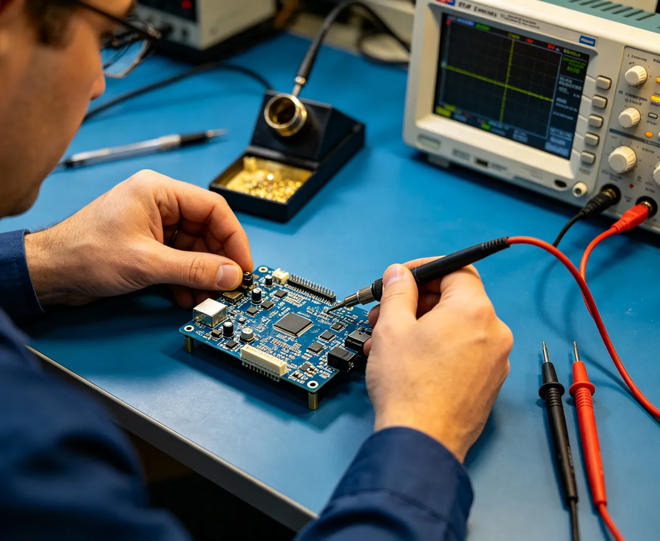
44 — Oscilloscope & Electrical Characterization
Hardware validation should move beyond simple continuity testing.
Depending on the product, engineers may characterize:
power-rail ripple
startup sequence
switching nodes
clocks
reset timing
PWM
serial interfaces
analog signals
The objective is to compare: Designed Behavior with Measured Behavior.
45 — High-Speed Interface Validation
For demanding systems, validation may involve:
Not every product requires all of these.
The test depth should match:
Data Rate + Risk + Compliance Requirement + Product Value.
Measure What Matters for the Actual Channel.
46 — Power Integrity Validation
Prototype validation can examine:
DC rail accuracy
ripple
transient response
power sequencing
current consumption
load behavior
thermal behavior
Measurements can be correlated with simulation or calculated design assumptions.
The objective is: Close the Loop Between Power Design and Real Hardware.
47 — Thermal Validation
Thermal validation may use:
temperature probes
thermal cameras
embedded sensors
controlled loads
environmental chambers
Test conditions should reflect realistic:
Ambient Temperature
Compute Load
Power Load
Enclosure
Airflow
The critical question is not: Does the board run at room temperature with the enclosure open?
It is: Does the Complete Product Maintain Sufficient Thermal Margin in Its Real Operating Environment?
48 — EMC Pre-Compliance Engineering
Waiting until formal compliance testing to discover fundamental EMC problems is expensive.
Pre-compliance work may identify:
radiated emissions
conducted emissions
ESD weaknesses
immunity concerns
cable-related noise
Corrective actions may involve:
Circuit
PCB
Filter
Grounding
Cable
Enclosure
Firmware
The earlier EMC problems are found, the easier they usually are to fix.
49 — EVT Hardware Validation
Does the Engineering Architecture Work?
EVT can focus on fundamental design feasibility.
Questions include:
Does the processor boot reliably?
Does memory work?
Are power rails stable?
Do interfaces operate?
Are sensors functional?
Is RF functional?
Is thermal performance acceptable?
Are major architecture assumptions correct?
EVT is where engineering risk should be exposed.
EVT Is for Learning — Not Pretending the Product Is Finished.
50 — DVT Hardware Validation
Does the Mature Design Meet the Product Requirements?
DVT may evaluate:
complete functionality
electrical performance
EMC
thermal performance
environmental behavior
mechanical integration
wireless performance
power consumption
reliability
user scenarios
The hardware should become increasingly stable.
Changes after this stage need tighter control.
51 — PVT & Production Validation
Can the Factory Build the Product Repeatedly?
PVT shifts attention toward:
manufacturing process
assembly
programming
test fixtures
cycle time
traceability
first-pass yield
production documentation
A hardware design is not truly finished when one prototype works.
It Is Finished When a Controlled Process Can Build It Repeatedly.
52 — NPI & Design Transfer
The transition to manufacturing can include:
Schematic
PCB
BOM
Firmware
Mechanical Data
Assembly Instructions
Programming Files
Test Procedures
Golden Sample
Revision Control
Control Plan
365PCB's ODM advantage should be the ability to connect this engineering package directly with the manufacturing system.
Design Transfer Is Where Engineering Becomes Production.
53 — Hardware Revision Control
Embedded products evolve.
A disciplined program should control relationships between:
Hardware Revision
PCB Revision
BOM Revision
Firmware Revision
Mechanical Revision
Test Revision
A component substitution or layout change can affect several of these simultaneously.
Therefore: Configuration Control Is Part of Hardware Reliability.
54 — Component Lifecycle Engineering
Embedded hardware may remain in production for years.
Platform selection should therefore consider:
A great architecture that cannot be manufactured three years later is not a great product architecture.
Design for the Lifecycle — Not Just the Launch.
55 — Product Family & Hardware Platform Design
High-level embedded hardware can be designed as a reusable platform.
For example:
This can support multiple SKUs with greater reuse.
Potential benefits include:
Build a Product Platform, Not Just One PCB.
56 — Designing for Future Performance
Good architecture can reserve appropriate margin for future:
firmware growth
memory growth
additional sensors
connectivity
AI features
higher data throughput
But overdesign also has a cost.
Therefore margin should be deliberate.
Engineer the Right Headroom — Not Unlimited Headroom.
57 — Hardware for Edge AI
Edge AI platforms can place especially difficult demands on hardware.
They may require: Camera / Sensor → High-Speed Input → Preprocessing → NPU / GPU → Memory → Inference → Output
Challenges include:
compute performance
memory bandwidth
camera interfaces
high-speed routing
power
thermal management
storage
networking
For AI hardware: TOPS Alone Does Not Define a Good Product.
The real system must balance: Inference Performance + Power + Memory + Latency + Thermal + Cost.
58 — Hardware for Robotics & Real-Time Control
Robotics hardware often combines:
high-level compute
real-time MCU
motor control
encoders
IMU
cameras
sensors
CAN / Ethernet
safety monitoring
The architecture can separate:
High-Level Intelligence
Navigation
Vision
Planning
from:
Deterministic Control
Motor loops
Sensor timing
Safety response
This is another example where heterogeneous architecture becomes valuable.
59 — Hardware for Industrial Electronics
Industrial hardware may need greater emphasis on:
wide input voltage
isolation
EMC
surge
ESD
long lifecycle
industrial communication
thermal robustness
diagnostics
The design should reflect the actual industrial environment rather than applying consumer-electronics assumptions.
Environment Changes Architecture.
60 — Hardware for Long-Life Products
Long-life electronic platforms require deliberate design choices.
Engineering may prioritize:
sustainable components
margin
thermal control
protection
diagnostics
replaceable modules
revision management
second sourcing
The objective is not merely long service life.
It is long: Manufacturable Life + Supportable Life + Reliable Life.
What Does World-Class Embedded Hardware Design Look Like?
At the highest level, embedded hardware engineering should connect: Product Requirements → System Architecture → Compute Architecture → Hardware / Software Partitioning → Memory → Power → Clock / Reset → Analog / Sensors → High-Speed Interfaces → RF / Wireless → Security → SI / PI → EMC → Thermal → PCB → DFM / DFA / DFT → Prototype → Bring-Up → Electrical Characterization → EVT → DVT → PVT → NPI → Stable Production
That is the difference between: Designing a PCB and Engineering an Embedded Product Platform.
Typical Embedded Hardware Design Deliverables
Depending on project scope, a 365PCB ODM hardware program may include:
Hardware Requirements Specification
Hardware Architecture
System Block Diagram
Processor Platform Evaluation
MCU / MPU / SoC Selection
FPGA / NPU Architecture Inputs
Memory Architecture
Power Tree
Power Budget
Power Sequencing Plan
Clock Architecture
Reset Architecture
Interface Definition
Analog Front-End Architecture
Sensor Interface Design
Communication Interface Design
RF Integration Requirements
Hardware Security Architecture
Debug Architecture
Programming Architecture
Schematic Design
PCB Design Constraints
Stack-Up Requirements
High-Speed Constraint Definition
SI / PI Analysis Plan
DFM Review
DFA Review
DFT Plan
Test-Point Strategy
Hardware Bring-Up Plan
Prototype Test Plan
EVT Validation Plan
DVT Validation Plan
PVT Inputs
BOM
AVL / Approved Alternates
Component Lifecycle Review
Hardware Design Review Report
Engineering Change Documentation
NPI Design Transfer Package
The exact deliverables should be adapted to the complexity, risk and lifecycle of the actual product.
What Can You Bring to 365PCB?
You can begin with:
or simply: Tell Us What the Electronics Need to Do.
From there, engineering can work through: Architecture → Circuit → PCB → Firmware Interface → Prototype → Validation → Production.
Design Hardware That Works.
Engineer Hardware That Survives.
Validate Hardware That Can Be Manufactured.
Build Hardware That Can Scale.
365PCB Embedded Hardware Design connects: System Architecture + Electronics + PCB + Firmware + Manufacturing
into one integrated product-development process.
We do not want the result to be a board that only works on the engineer's bench.
We Want It to Become a Reliable Product Platform Ready for Production.
 English